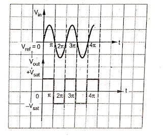
Electronic oscillator division types and use Electronic oscillator division types and use Introduction to oscillator An oscillator is a amplifier and it is a close loop circuit or network. It uses the Positive feedback. It is not require the externel signel and generate the a desired frequency A oscillatpr acts like generator, It oscillates the constant amplitude and frequency. Oscillator can generate the frequency upto gigahertz. Classification of the Oscillators Oscillators are classified based on the type of waveforms generate from the oscillator, range, frequency, parameters used. Based on Output waveforms. Based on circuit components. Range of operating frequency. Based on feedback uses or not uses Types of oscillatprs LC Oscillator Har...


Comments
Post a Comment